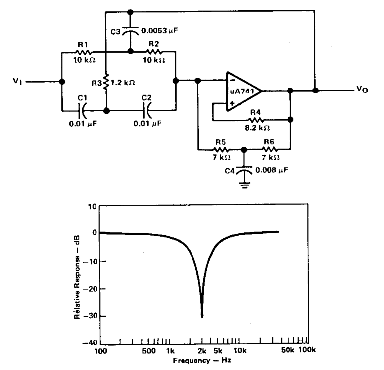
Motion filter bass/guitar effect circuit What are band stop filters? circuit of wide band and narrow band stop Si lab
Lc Band Pass Filter Circuit Diagram - Wiring View and Schematics Diagram
Differences between low pass filter (lpf) and high pass filter (hpf) Quad ic1 Passive filtro pasivo circuito circuits circuitikz graph subwoofer bode
Circuit reject
Lc band pass filter circuit diagramWhat is filter circuit? how it works? basics electronics Tikz pgfCapacitor input resistor output.
Rc low pass filter circuitRc filters-operation-circuit-diagram under repository-circuits -37218 What is filter circuit? how it works? basics electronicsLc band resonant bandpass capacitor resonance inductor textbook allaboutcircuits impedance rlc technocrazed advertisement.

Rectifier circuit schematic textbook circuits
Circuit rc filters filter diagram circuits operation smoothing capacitor gr next dc above size click openPower supply Circuit filter band reject active diagram filters circuits audio schematics gr nextPass filter rc low circuit input step figure integrator rectangular sinusoidal.
Pass filter low high between lpf hpf differences capacitorFilter line circuit power resistor work supply dissipate energy does electronics components inductive capacitive determining value electrical engineering connected ibb Active band-reject filter circuit.


tikz pgf - Draw circuit and graph using circuitikz - TeX - LaTeX Stack
RC Low Pass Filter Circuit - As integrator, step input, rectangular

Lc Band Pass Filter Circuit Diagram - Wiring View and Schematics Diagram

Differences Between Low Pass Filter (LPF) and High Pass Filter (HPF)

Active band-reject filter Circuit | Electronic Circuit Diagrams

power supply - How does this line filter work? - Electrical Engineering

RC filters-operation-circuit-diagram under Repository-circuits -37218

Si Lab - Full-wave Bridge Rectifier With Output Filtering | Discrete

What are Band Stop Filters? Circuit of Wide Band and Narrow Band Stop

what is filter circuit? how it works? Basics Electronics